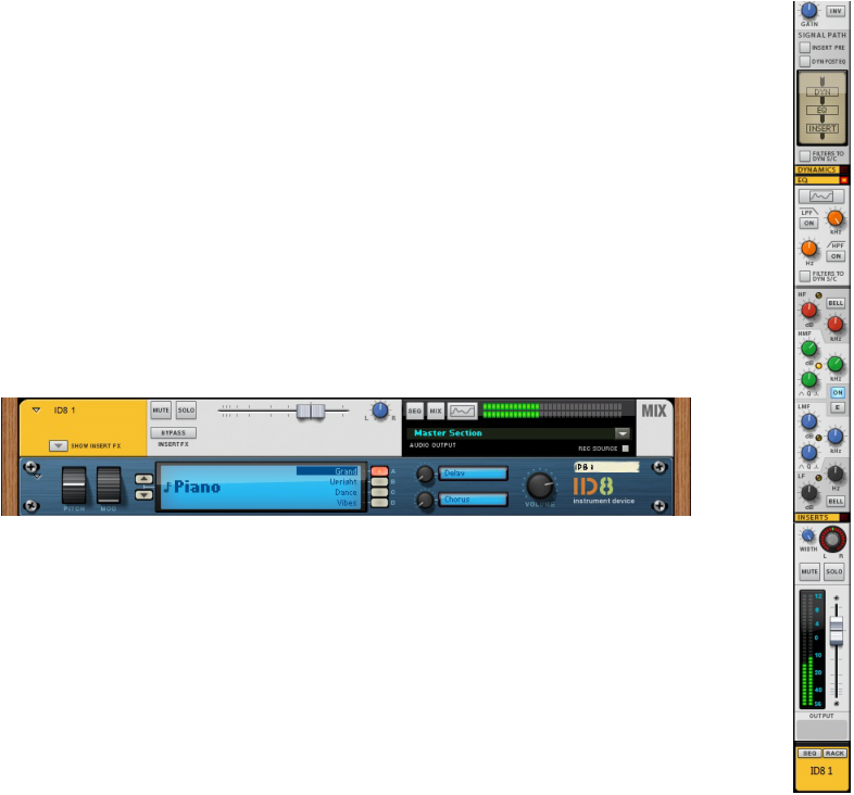
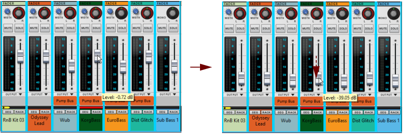
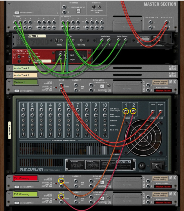
A Mix Channel device acts as a host to a source device (e.g. an instrument device). When you create an instrument, a Mix Channel device is added automatically to the rack and a corresponding Mix Channel strip is added to the Main Mixer. You can also create Mix Channels manually from the Utilities tab in the Device Palette - or from the Create menu. This is useful if you need to make manual mixer routings - see “Advanced routing tips and tricks” at the end of this chapter.
The Mix Channel device has inputs to which the source (instrument) device is connected. The Mix Channel device and channel strip will automatically be assigned the name of the connected source device, but this can be changed - see “Naming mixer channels”.
A Mix Channel device will not automatically have a corresponding track created in the sequencer (but the connected source device will). Mix Channel tracks are created manually and used for automating channel strip parameters - see “Automating mixer parameters”.
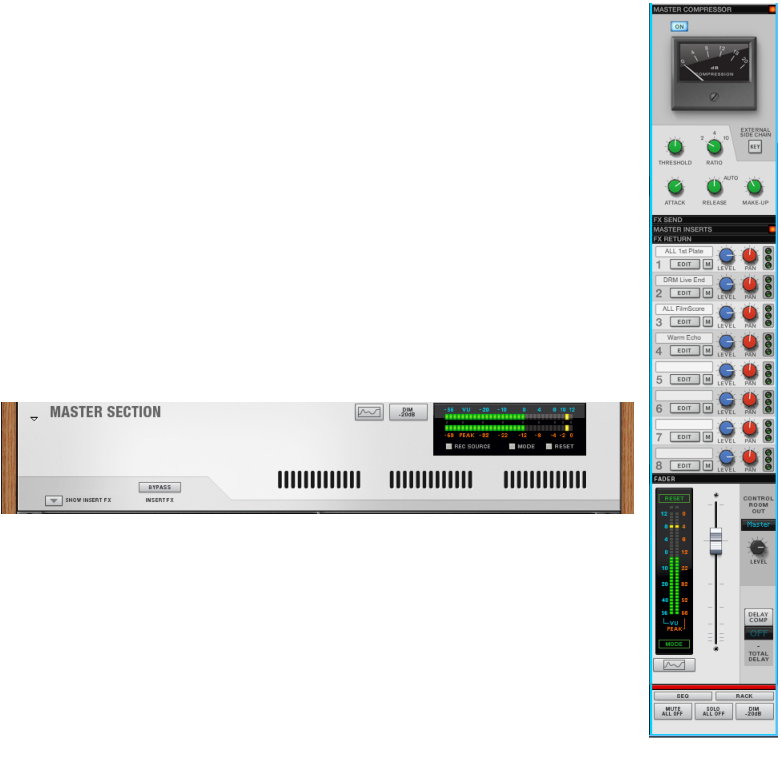
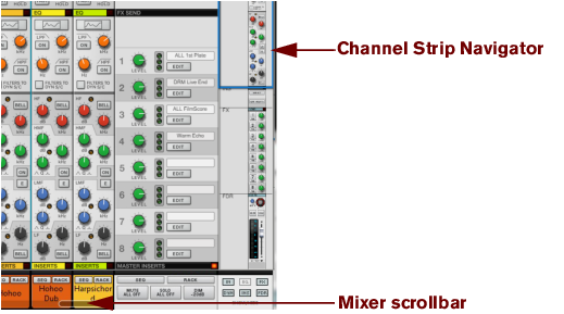
The Master Section device is always present and is fixed in the rack, just below the Reason Hardware Interface. This is where all your Audio Track and Mix channels are summed and mixed to stereo, and where you set up your Send effects and Master Insert effects. For descriptions of how to set up and use effects, see “Insert FX” and “Send FX”.
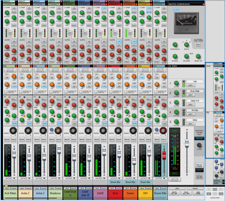
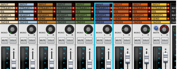
Each section has a section name header in the channel strip. The sections are as follows (from the top down): Input, Dynamics, EQ, Inserts, FX Sends and Fader. (See “The channel strip” for descriptions of each section.)
The channel will get Edit Focus (see “Channel Header section”) and be scrolled into view in the Main Mixer. If you have both the sequencer and Main Mixer in view, or the rack and Main Mixer, clicking a track in the Track List, or on a Mix Channel/Audio Track device in the rack, will flash the corresponding channel strip in the Main Mixer.
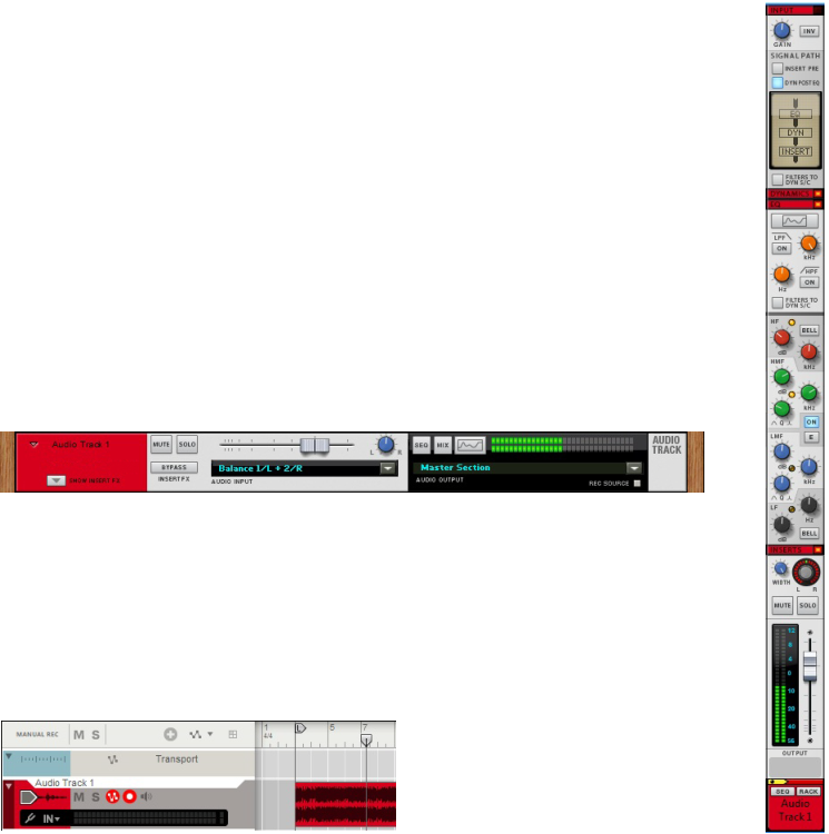
Mixer channel strips are automatically created when you create Audio Track and Mix Channel devices. In most situations, a Mix Channel device (with its channel strip) is also automatically created when you create an instrument device (see “Creating devices”).
If there are devices connected to the Mix Channel device you delete, and “Auto-group Devices and Tracks” is selected on the Options menu, the alert will ask if you want to delete only the selected device, or all devices in the Device Group (see “Creating devices” for more information).
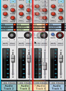
This allows you to e.g. change the Fader levels of all selected channels simultaneously (see “Changing Fader section parameters on multiple channels simultaneously”), or move or delete several channels in one go. The last selected channel will be given edit focus which is indicated by a red strip in the channel header (see “Channel Header section”).
|
|
|
|
Resetting channel settings initializes all channel strip parameters to default values and removes any insert effects (see “Insert FX section”) from the channel.
|
|
|
|
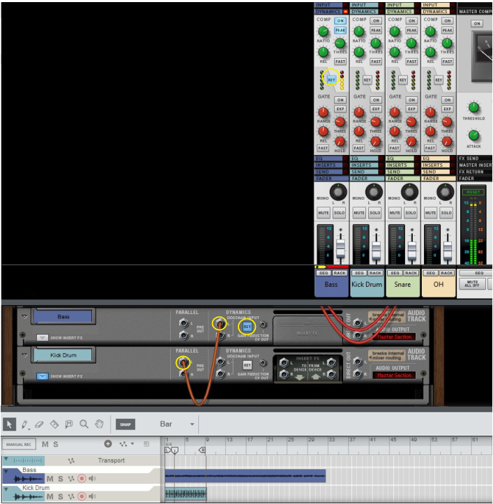
See “Using compression sidechaining” for a description of further uses of sidechaining.
|
1.
|
|
|
The Insert effects can be placed ahead of the Dynamics and EQ sections in the signal path, see “Signal Path section”.
|
•
|
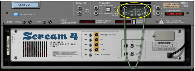
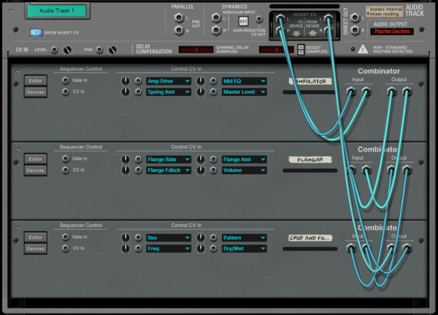
See “Insert FX” for descriptions of how to create and work with Insert effects.
|
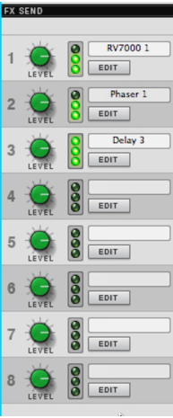
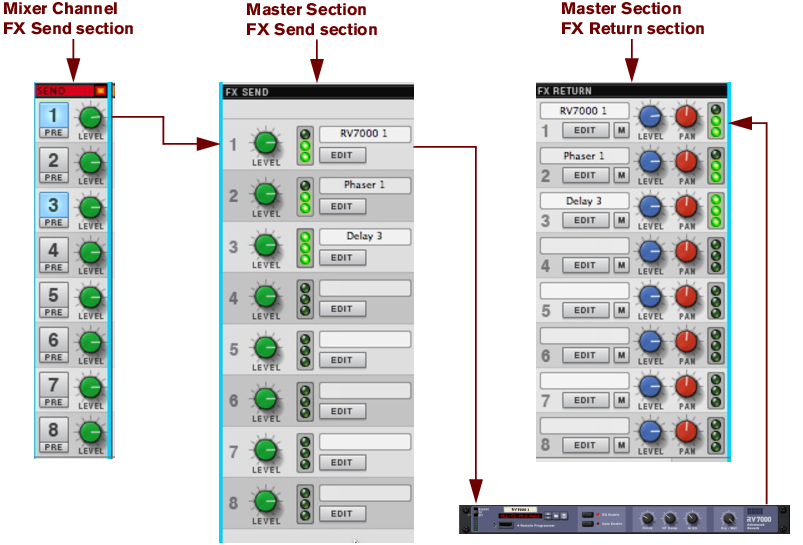
Send effects, which are global for all channels in the Main Mixer, are connected to the Master Section rack device. Up to 8 Send effects can be used simultaneously. For a description of how to use Send effects, see “Send FX”.
|
|||||||
|
|||||||
|
|||||||
|
|
|
•
|
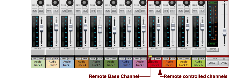
The Remote Base Channel indicator - To the left in the same horizontal strip area a small yellow arrow symbol can be shown. This is the Remote Base Channel indicator, which shows which channel is considered the first or base channel when using Remote Control - see “Setting the Remote Base Channel”.
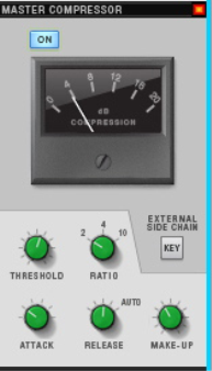
The Master Compressor can be applied pre or post Master Insert section - see “Master Inserts section”.
|
| Range
|
||||
|
|
•
|
See “Insert FX” for descriptions of how to create and work with Insert effects.
|
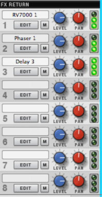
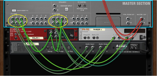
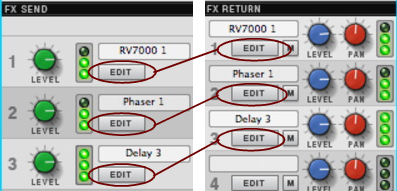
This section controls the master levels of the FX Returns. Send effect devices are connected to the Master Section via the eight FX Send and eight FX Return connectors on the Master Section device. See “Send FX” for a description of Send FX.
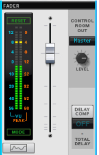
The Control Room outputs are located on the back of the Master Section device. To use the Control Room output section, the outputs have to be connected to your monitor system. This can be done by manually patching cables from the “Ctrl Room Out” connectors to a separate output pair on the Reason Hardware Device - see “Manual audio routing”.
The total delay of the Main Mixer signal (at the Master Out) is displayed below the display. See the “Delay Compensation” chapter for more information about delay compensation in Reason.
By definition, insert effects are inserted in the signal chain and process the whole channel signal, as opposed to Send effects (see “Send FX”) where the effect is shared among all channels and the balance is individually adjustable for each channel. Typical insert effects are dynamics, distortion, chorus etc., plus mastering effects for the Master Section.
|
|
|
|
|
•
|
|
3.
|
An alert appears asking you to confirm the deletion. (See “Deleting devices” for more details).
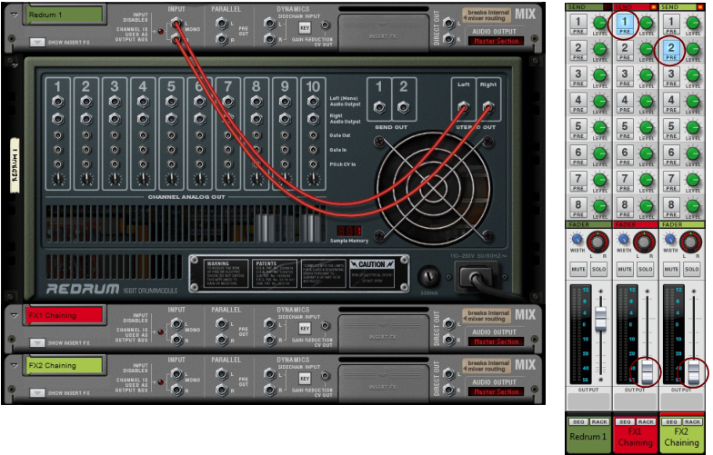
Send effects are routed in parallel with the signal chain, and the effect balance can be adjusted - as opposed to Insert effects, which are inserted in the signal chain and process the whole channel signal (see “Insert FX”). Typical Send effects include reverbs and delays.
|
•
|
An alert appears asking you to confirm the deletion. (See “Deleting devices” for more details).
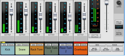
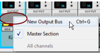
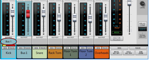
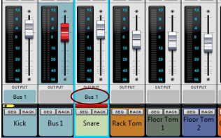
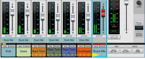
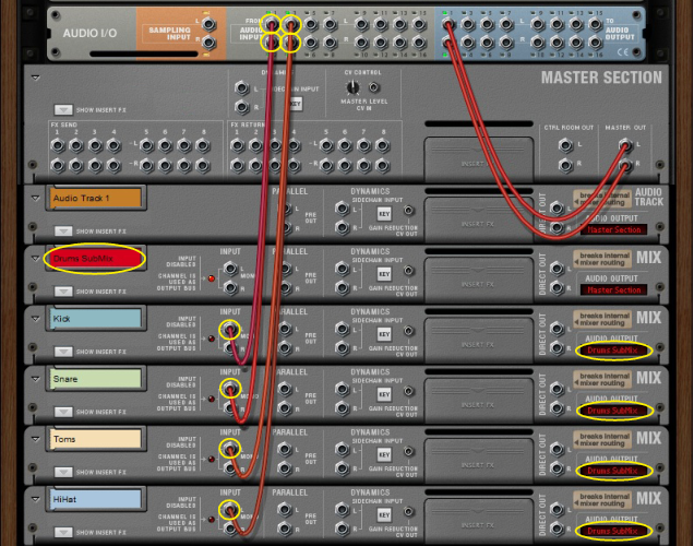
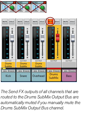
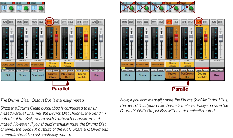
Output Busses allow you to create sub-mixers. Sub-mixers can be very useful for pre-mixing a multi-mic’ed drum kit, or a horn section, for example. You can also use a sub-mixer configuration to route several external input signals (from separate microphones, for example) for recording onto a single audio track (see “Recording a sub-mix onto an audio track”). You can have as many mix busses as you like in a Reason song.
See “Recording audio from Mix Channel outputs” for more details.
|
|
|
4.
|
Functions for changing the Remote Base Channel may already be mapped to buttons on your control surface - see the “Control Surface Details” pdf document. If not, you can set this up manually in the Additional Remote Overrides dialog on the Options menu - see “Additional Remote Overrides...”.
If your control surface doesn’t have buttons already assigned for controlling Remote Base Channel selection, you can manually assign controllers for this by using the Remote Override function described in “Remote Override mapping”. Alternatively, select a channel strip and select “Set Remote Base Channel” from the Edit menu or context menu.
See “Remote - Playing and Controlling Devices” for more details about remote controlling Reason. See also the “Control Surface Details” pdf document for information about parameter assignments on various common control surfaces.
|
•
|
Use a “Spider Audio Merger & Splitter” device to split the sidechain signal from the Parallel outputs and/or Insert FX “To Device” output into several signals.
|
See “Output Busses” for information.
Another typical application for compression sidechaining is to use the internal signal of the channel, filter it, and then feed to the compressor via “internal” sidechaining. This type of internal sidechaining can be used for de-essing, for example. No additional patching is required for this; you only have to activate the “Filters to Dynamics Sidechain” button in the Filter or EQ sections. See “About the Filters To Dynamics Sidechain button”.
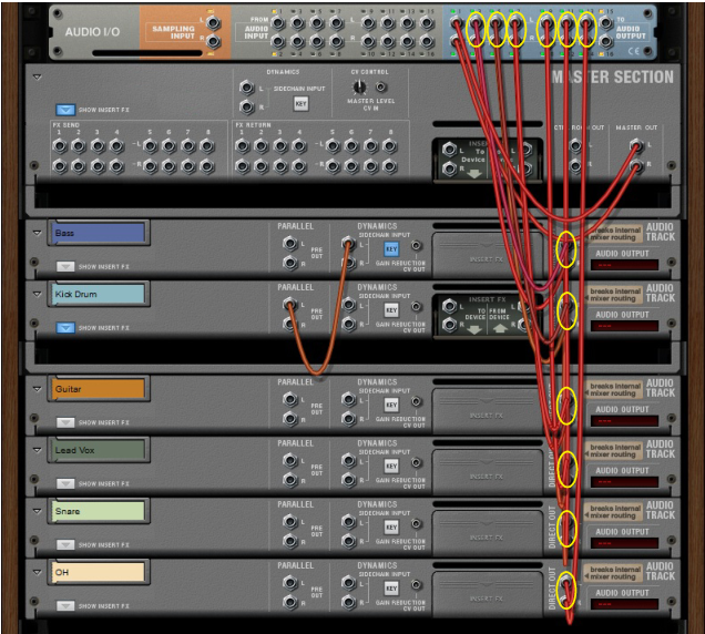
Direct routing of individual channel outputs to individual outputs on the Reason Hardware Interface.
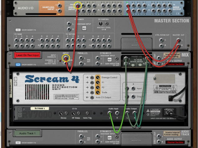
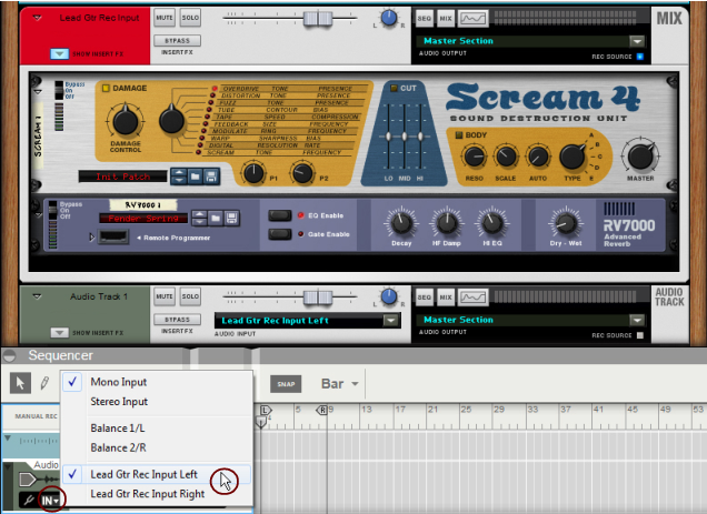
Now, you can begin recording on the Audio Track according to the standard recording procedures described in “General recording procedure”. The signal will be processed by the Insert FX of the Mix Channel device before being recorded on the track.
